

Best Earth Resistance Testers in 2026: A Complete Buyer’s Guide
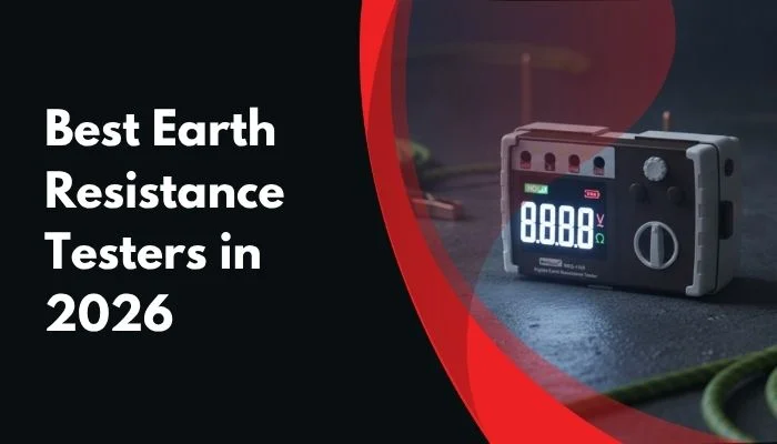
Updated for 2026: This guide compares practical earth resistance testing methods and selected MarMonix grounding testers based on the technical information available in their product documents.
An effective grounding system is essential for electrical safety, fault-current dissipation, lightning protection, and the reliable operation of industrial equipment. However, a grounding system cannot be judged by appearance alone. It must be tested with a suitable earth resistance tester.
Also known as a ground tester, earth ground tester, or ground resistance meter, this instrument measures the resistance between a grounding electrode and the surrounding soil. The result helps technicians determine whether the grounding system is performing within the required limits for the installation.
In this guide, you will learn how earth resistance testers work, which testing method is suitable for each application, what factors affect the measurement, and how to choose between the MarMonix MEG 4105, MEG725, MEG-825, and MEG-925.
Important: There is no universal earth resistance value that automatically applies to every installation. Always compare the measured result with the applicable electrical code, project specification, utility requirement, or site standard.
What Is an Earth Resistance Tester?
An earth resistance tester measures the resistance of a grounding electrode or grounding network to the surrounding earth. The measured value is normally expressed in ohms (Ω). A lower resistance generally indicates a more effective path for fault current, although the acceptable value depends on the type of installation and the governing standard.
The measurement is affected by several factors, including soil resistivity, moisture, temperature, electrode depth, electrode spacing, corrosion, conductor connections, and the overall design of the grounding network.
Because soil conditions change during the year, a grounding system may produce different readings during wet and dry seasons. This is why professional maintenance programs often include periodic testing and trend analysis rather than relying on one isolated measurement.
Why Is Earth Resistance Testing Important?
A properly tested grounding system helps protect personnel, electrical equipment, control systems, and communication infrastructure. Earth resistance testing can help identify a deteriorated electrode, a loose connection, a damaged conductor, or a grounding system that is no longer suitable for the current installation.
- Provides a low-resistance path for fault current.
- Supports the correct operation of protective devices.
- Helps reduce dangerous touch and step voltages.
- Supports lightning and surge protection systems.
- Helps identify grounding deterioration before a failure occurs.
- Provides documented test results for maintenance and compliance records.
Earth Resistance Test Methods Compared
The correct tester depends largely on the grounding arrangement and the required measurement method. The most common approaches are the three-point fall-of-potential method, the four-point soil-resistivity method, clamp-on testing, and selective testing.
| Test Method | Best Application | Auxiliary Stakes | Disconnection | Main Advantage |
|---|---|---|---|---|
| 3-Pole Fall-of-Potential | Isolated electrodes and commissioning | Yes | Usually required | Established reference method |
| 4-Pole Wenner | Soil resistivity and grounding design | Yes | Not applicable | Evaluates soil before installation |
| Clamp-On / Stakeless | Bonded and multi-grounded systems | No | No | Fast testing without disconnecting the conductor |
| Selective Testing | Testing one electrode in a connected system | Yes | Not always | Targeted testing with reduced disruption |
3-Pole Fall-of-Potential Testing
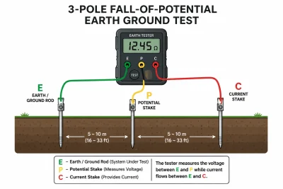
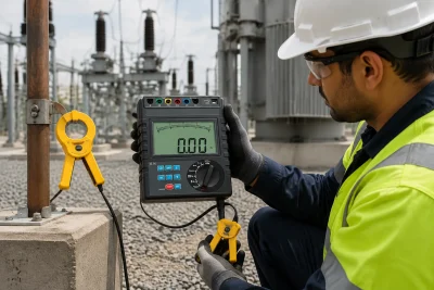
The three-point fall-of-potential method is commonly used for isolated grounding electrodes. It uses the electrode under test and two auxiliary stakes. The tester injects a test signal through the soil and measures the resulting voltage to calculate resistance.
This method is suitable when the grounding electrode can be isolated and there is enough space to place the auxiliary stakes at suitable distances.
4-Pole Soil Resistivity Testing
Four-point testing is primarily used to measure soil resistivity before designing a grounding system. Soil-resistivity information helps engineers determine the required electrode depth, spacing, grid configuration, and other design parameters.
Clamp-On or Stakeless Testing
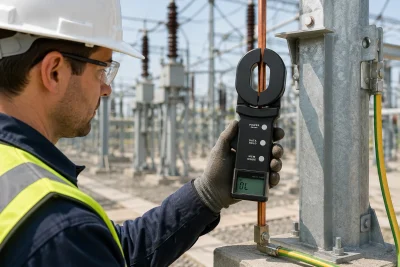
Clamp-on testing is useful in systems containing multiple parallel grounding paths. The clamp applies and measures the test signal through the grounding loop, allowing technicians to test suitable systems without disconnecting the grounding conductor or installing auxiliary stakes.
Clamp-on testing is especially useful for routine inspections of power distribution systems, telecommunications sites, industrial facilities, lightning-protection systems, and other connected grounding networks.
What Is a Good Earth Resistance Value?
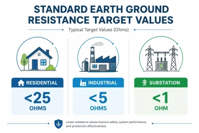
The acceptable earth resistance value depends on the application, local regulations, project requirements, and the design of the electrical installation. The following values are general engineering reference points, not universal pass/fail limits.
| Application | Common Reference Range | Important Note |
|---|---|---|
| General electrical installations | Up to approximately 25 Ω | Confirm against the applicable standard. |
| Commercial and industrial facilities | Often 5–10 Ω or lower | Project specifications may be stricter. |
| Data centres and sensitive electronics | Often 5 Ω or lower | Grounding design and bonding are also critical. |
| Substations and lightning protection | Often 1–5 Ω | Use the utility or engineering specification. |
Best practice: Record the test value together with the date, temperature, soil condition, test method, electrode location, and instrument model. Trend data is often more useful than a single reading.
How to Measure Earth Resistance Correctly
- Identify the grounding arrangement. Determine whether the system is isolated, bonded, multi-grounded, or connected to a grounding network.
- Select the appropriate method. Use a three-wire or four-wire method when stakes are practical, or clamp-on testing for suitable connected grounding systems.
- Follow electrical safety procedures. De-energize and verify the circuit whenever the test procedure requires disconnection or direct access to conductors.
- Inspect the connections. Clean contact points, tighten loose connections, and check the condition of test leads and clamps.
- Place auxiliary stakes correctly. For fall-of-potential testing, place the current and potential stakes in accordance with the instrument manual and site conditions.
- Take multiple readings. Confirm that the result is stable and repeatable. Unexpected fluctuations may indicate interference, poor contact, unsuitable spacing, or an inappropriate test method.
- Document the result. Store or record the value with the location, test method, weather, soil conditions, and equipment details.
Safety warning: Never clamp a standard clamp grounding tester around an energized power line unless the instrument documentation specifically permits that procedure. Follow the manufacturer’s safety instructions and applicable site lockout/tagout procedures.
How to Reduce High Earth Resistance
If the measured resistance is higher than the required limit, first confirm that the test method, lead connections, stake spacing, and instrument settings are correct. A poor connection or unsuitable test arrangement can produce an unreliable result.
Depending on the installation, corrective measures may include:
- Driving the grounding electrode deeper.
- Installing additional bonded electrodes with suitable spacing.
- Using a grounding grid or grounding plates.
- Improving the soil around the electrode with an appropriate conductive material.
- Repairing corroded or loose conductors and connections.
- Re-testing the installation after every corrective action.
Best MarMonix Earth Resistance Testers Compared
MarMonix offers different grounding testers for traditional stake-based measurements, fast clamp-on testing, and professional multi-method field inspections. The best model depends on the grounding network, required test method, documentation needs, and the level of measurement flexibility required.
| Model | Tester Type | Verified Functions | Notable Features | Best For |
|---|---|---|---|---|
| MEG 4105 | Digital lead-based earth tester | Ground resistance and ground voltage | 20 Ω, 200 Ω, and 2000 Ω ranges; two-wire and three-wire testing; backlight; Data Hold; IP40 | Routine testing of isolated grounding electrodes |
| MEG725 | Clamp-on ground resistance tester | Ground resistance; current measurement for C type only | 0.01–1000 Ω resistance range; 55 × 32 mm jaw; 99-record memory; alarm; approximately 0.5-second measurement | Fast testing of suitable bonded and multi-grounded systems |
| MEG-825 | Multi-function ground resistance clamp meter | Ground resistance, soil resistivity, grounding current, and grounding voltage | Two-, three-, and four-wire methods; FFT; AFC; 500-result memory; Bluetooth; Android application; colour LCD | Professional inspection, reporting, and multi-method testing |
| MEG-925 | Technical details pending verification | Do not publish unverified functions | The available manual did not provide readable specifications | Confirm the full datasheet before technical comparison |
MarMonix MEG 4105 Digital Earth Resistance Tester
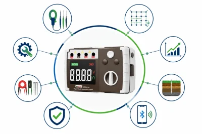
The MarMonix MEG 4105 is a conventional digital earth resistance tester designed for two-wire and three-wire measurements. It provides ground-resistance ranges of 20 Ω, 200 Ω, and 2000 Ω, together with ground-voltage measurement up to 200 V.
The MEG 4105 provides range-specific resolution and accuracy, a poor-contact safety alert, ground-voltage overload protection, Data Hold, backlight, battery checking, and an IP40 housing. Its field kit includes test leads, auxiliary ground stakes, batteries, a carrying strap, and a protective bag.
This model is a practical choice for technicians who need a straightforward, portable tester for conventional grounding inspections and isolated electrode testing.
MarMonix MEG725 Clamp-On Ground Resistance Tester
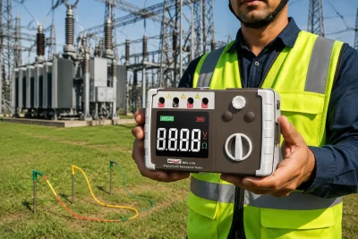
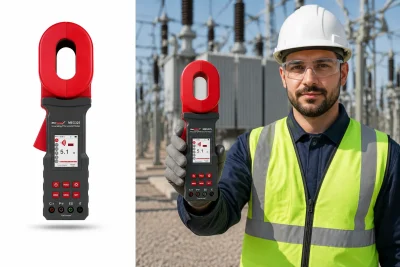
The MarMonix MEG725 is a clamp-on ground resistance tester for suitable looped, bonded, and multi-grounded systems. Its clamp-based method can measure grounding resistance without disconnecting the grounding down-lead or installing auxiliary grounding electrodes.
The verified resistance measurement range is 0.01–1000 Ω, with a maximum resolution of 0.001 Ω. The instrument has a 55 × 32 mm jaw, automatic range shifting, an alarm function, approximately 0.5-second measurement time, and storage for 99 groups of results.
Current measurement is specified as 0–30 A for C type only. This limitation should be clearly stated in product content and should not be presented as a universal feature of every MEG725 configuration.
The MEG725 is suitable for routine grounding inspections in power, telecommunications, construction, industrial electrical, oilfield, meteorological, and lightning-protection applications. It should not be described as explosion-proof, waterproof, or suitable for clamping directly around a power line unless the applicable product documentation explicitly permits that procedure.
MarMonix MEG-825 Multi-Function Ground Resistance Clamp Meter
The MarMonix MEG-825 is identified in its datasheet as a multi-function ground resistance clamp meter and a member of the MEG-800 series. It is designed for more advanced field work where technicians may need several grounding measurement methods and better result documentation.
The datasheet lists ground resistance, soil resistivity, grounding current, and grounding voltage measurement. It also identifies clamp-meter, two-wire, three-wire, four-wire, and selection methods.
For field documentation, the MEG-825 includes automatic storage for 500 test results with date and time, Bluetooth communication, Android application support, a 2.5-inch colour LCD, a rechargeable lithium battery, USB charging, FFT technology, and AFC automatic frequency control.
Numeric measurement ranges, accuracy, resolution, clamp jaw dimensions, CAT rating, and IP rating were not visible in the available readable datasheet text. Therefore, those specifications should be confirmed from the final manufacturer specification table before publication.
MarMonix MEG-925
The MEG-925 is part of the MarMonix grounding tester range, but the available manual did not provide a readable specification table for verifying its technical functions, ranges, accuracy, clamp dimensions, safety ratings, battery details, or accessories.
For this reason, the MEG-925 should not be promoted with precise technical claims until a readable official datasheet or specification page is available. It may be listed as a related model, but its comparison should remain limited to verified information.
The MEG-825 datasheet includes a shared package heading referring to “MEG 825 / MEG 925.” However, this does not prove that both models have identical technical specifications. The models should therefore be kept separate in the product comparison.
Which MarMonix Earth Resistance Tester Should You Choose?
Choose MEG 4105 If:
You need a conventional two-wire or three-wire tester for isolated electrodes, commissioning, and routine grounding checks.
Choose MEG725 If:
You need fast clamp-on resistance testing on suitable bonded or multi-grounded systems without auxiliary stakes.
Choose MEG-825 If:
You need multiple test methods, soil-resistivity testing, result storage, Bluetooth communication, and Android reporting support.
Consider MEG-925 If:
You can obtain and verify the complete official technical specification before making a purchasing decision.
What to Look for When Buying an Earth Resistance Tester
Before buying a ground resistance tester, compare the following factors instead of focusing only on the lowest price or the largest resistance range.
- Measurement method: Confirm whether you need two-wire, three-wire, four-wire, clamp-on, or selective testing.
- Grounding arrangement: Clamp-on testing requires a suitable grounding loop or parallel return path.
- Resistance range and accuracy: Review accuracy at the actual resistance range used in your application.
- Soil-resistivity function: This is important for grounding design and site surveys.
- Data storage and communication: Memory, date/time records, Bluetooth, and mobile applications simplify reporting.
- Safety and environmental protection: Check the manufacturer’s safety category, enclosure rating, operating temperature, and application limitations.
- Accessories: Lead-based testing may require long test leads and auxiliary ground stakes.
- After-sales support: Calibration, technical support, spare parts, and warranty service are important for professional use.
How Often Should Earth Resistance Be Tested?
Annual testing is a useful minimum for many installations, but critical facilities may require more frequent inspection. Testing should also be considered after lightning strikes, grounding modifications, major electrical work, flooding, excavation near the grounding system, or noticeable changes in electrical performance.
Facilities with dry, corrosive, rocky, or seasonally variable soil may benefit from a more detailed testing schedule. Maintaining historical results allows maintenance teams to identify gradual increases in resistance before they become a serious safety issue.
Frequently Asked Questions About Earth Resistance Testers
Related Buyer’s Guides
- Best Digital Multimeters in 2026
- Clamp Meter vs Multimeter (2026)
- Best Insulation Resistance Testers in 2026
Part of: Electrical Test & Measurement Instruments — Complete Guide