

How to Test Insulation Resistance (Megger Test) Step-by-Step

Insulation failure is one of the most common root causes of electrical fires, unplanned downtime, and arc-flash incidents — and the fastest way to catch it early is the megger test, also known as an insulation resistance (IR) test. This guide walks you through how to test insulation resistance with a megger step by step, explains which DC test voltage to use for cables, motors, and transformers, and shows how to interpret your readings using IEEE 43-2013 guidelines such as the polarization index (PI).
For a wider selection of instruments for every test voltage and budget, browse our full range of insulation resistance testers.
What Is a Megger Test?
A megger test (insulation resistance test) measures how well the insulation of cables, windings and installations blocks current leakage. The tester applies a high DC voltage and calculates resistance from the resulting leakage current. Healthy insulation shows high resistance — typically in the megohm (MΩ) to gigohm (GΩ) range.
The full procedure is laid out step by step in the next section, so you can perform the test correctly and safely on the first attempt.
Why Insulation Resistance Testing Matters
Insulation degrades with age, heat, moisture and mechanical stress. A weak point lets current leak to earth or to adjacent conductors, raising the risk of:
- Electric shock to operators and users
- Short circuits and fires from tracking and overheating
- Equipment damage and unplanned downtime
Regular testing detects degradation before failure and documents safe operation for audits and insurance. Measuring the insulation resistance is the fastest way to confirm an installation is electrically sound.
Before You Start: Safety and Preparation
- De-energize and isolate the circuit under test; lock out the supply.
- Verify zero voltage with the tester’s voltage function before connecting.
- Connect test leads to the insulation tester and check the instrument leads themselves are sound.
- Perform the test in dry conditions where possible; moisture gives misleadingly low readings.
- Stand clear and avoid touching exposed conductors while the test voltage is applied.
Megger Test Step by Step
A megger test is only as reliable as the way it is performed. Applying the wrong test voltage, testing a live circuit, or skipping the pre-checks can give misleading readings — or damage the equipment. The five steps below walk you through the full procedure, from preparation to returning the installation to service, so your insulation resistance results are accurate and repeatable every time.
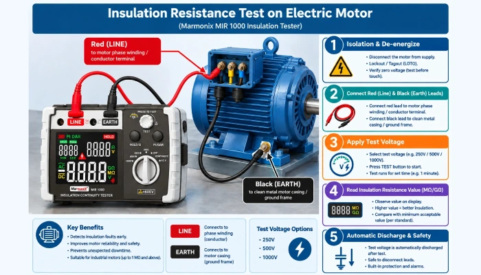
1. Prepare the Tester and Circuit
Select the correct test voltage for the application:
- 250–500 V — general low-voltage equipment and light commercial circuits
- 1000 V — most industrial LV installations, motors and distribution boards
- 2500 V — medium-voltage cables, transformers and switchgear
The MarMonix 30-2 offers 500/1000/2500 V; the MarMonix MIR 1000 covers 100/250/500/1000 V for lighter-duty work.

2. Connect the Test Leads
Connect the line and earth/alligator-clip leads to the tester and clamp them to the conductor and to earth or a known-good return path. For a motor or transformer, test between windings and frame.
3. Apply the Test Voltage and Log the Reading
Press the test button. The tester applies the selected DC voltage and displays the resulting insulation resistance. Record the value after the reading stabilizes (typically 1 minute; some tests read at 60 s for a polarization index).
Both the 30-2 and the MIR 1000 hold the reading and the MIR 1000 adds a PI/DAR function and over-limit “Hi” indication; the 30-2 auto-ranges to its 20 GΩ maximum.
4. Evaluate Against the Minimum Resistance
Compare the result with the minimum acceptable value:
- General rule of thumb: 1 MΩ per 1000 V of operating voltage.
- Many LV installations use a practical floor of 1 MΩ; industrial and certified work may require higher values.
Deeply aged or damp insulation on the 30-2’s upper range is immediately flagged; a weak spot shows as a low reading even before routine wear is visible.
5. Repeat, Document and Return to Service
Test each circuit phase-to-earth and phase-to-phase as required. Record results, date and the tester used. When finished, the tester auto-discharges the cable capacitance. Restore the supply only after all circuits pass.
Choosing Between the MarMonix 30-2 and MIR 1000
Both instruments cover everyday insulation work, but they target different duty. The 30-2 reaches 2500 V and 20 GΩ, making it the choice for medium-voltage cable and transformer testing. The MIR 1000 adds PI/DAR diagnostics, a dedicated continuity range and true voltage measurement (AC/DC), packed into a lighter-duty 5.5 GΩ instrument.

| Specification | MarMonix 30-2 | MarMonix MIR 1000 |
|---|---|---|
| Test voltages | 500 / 1000 / 2500 V | 100 / 250 / 500 / 1000 V |
| Insulation resistance range | 0–20 GΩ | 0–5.5 GΩ (1.5 GΩ @ 100 V) |
| Resistance accuracy | ±(3% + 5 dgt) | ±5% rdg ±3 dgt (above 100 kΩ) |
| Continuity / low resistance | Low-resistance buzzer | 0.0–999 Ω, ±(2% + 3), ~5.0 V open-circuit |
| Voltage measurement | AC 600 V, ±(2% + 5) | AC 30–600 V & DC ±30–±600 V, auto AC/DC |
| PI / DAR | — | Yes, dedicated button |
| Auto discharge | Auto-range, data hold, low battery | Yes, red-light & buzzer alarm, data hold |
| Power supply | 6 × AA 1.5 V | 6 × AA 1.5 V, ~12 h battery life |
| Display | LCD, 1999 counts | Large-screen LCD, 500 counts |
| Dimensions | 150 × 100 × 70 mm, ~680 g | 176 × 110 × 77 mm |
| Best for | MV cables, transformers, 2.5 kV work | General LV, PI monitoring, continuity |
Note: PI/DAR, continuity range, AC/DC voltage and battery-life figures apply to the MIR 1000 only; the 30-2 datasheet does not state these. Neither datasheet lists an IP or safety category (CAT/IEC) rating.
Frequently Asked Questions
What voltage should I use for a megger test?
Match the voltage to the application: 500 V for general low-voltage circuits, 1000 V for most industrial LV installations and motors, and 2500 V for medium-voltage cables, transformers and switchgear.
Is a megger test destructive?
No. It applies a fixed DC test voltage and measures leakage current. It is a non-destructive routine check that may reveal (not cause) an existing insulation weakness.
How often should insulation resistance be tested?
Typically every 1 to 3 years for installations, and annually after commissioning, major repairs or water damage. Set the final interval by certification requirements and equipment criticality.
What minimum insulation resistance value is acceptable?
A common rule is 1 MΩ per 1000 V of operating voltage, with a practical floor of 1 MΩ for many LV circuits. Follow the applicable standard and manufacturer specification.
What if insulation resistance is below the limit?
Locate and repair the fault: clean or replace damaged insulation, dry out wet components, and re-test. Low readings can also come from terminations, condensation or moisture ingress rather than the insulation itself.